
VSFX 755 - Procedural 3D Shader Programming
Outputting Secondary AOVs via a Renderman RSL Shader
Project Summary:
Use RSL's capabilities to demonstrate the variety of arbitrary output variables, or secondary images, it can generate. Create one based on Z-depth and use it in post-processing to show the purpose of such images.
Results:
Click on the image to the right to see a final video.
The Brief
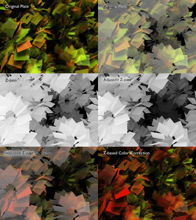
RSL and PRman have numerous AOVs built into their functionality allowing the output of various secondary images, like normals, S and T data, or specularity, for the purpose of compositing and post-processing. Another common data type needed is Z-depth, or distance of any point from the camera. While the renderer has options to output Z as an added channel automatically, there are certain strengths to being able to do so on an object by object basis, rather than the entire scene at once. Z-depth calculations can be incorporated into a specific shader's code so that only that object will register in the Z-pass.For this project I used the scene built for the conditional shader project because it offered dense geometry over a given depth. This way the variations in the z-pass, and therefore the post-processing based on it, would be easily evident. I used the Z-pass to create a false depth of field and for selective color correction.
Sample Images
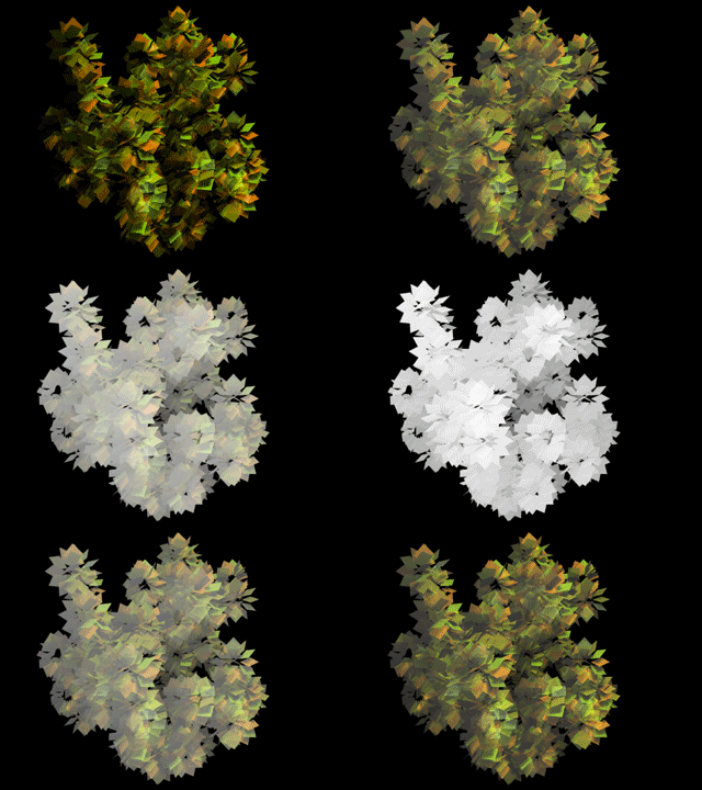
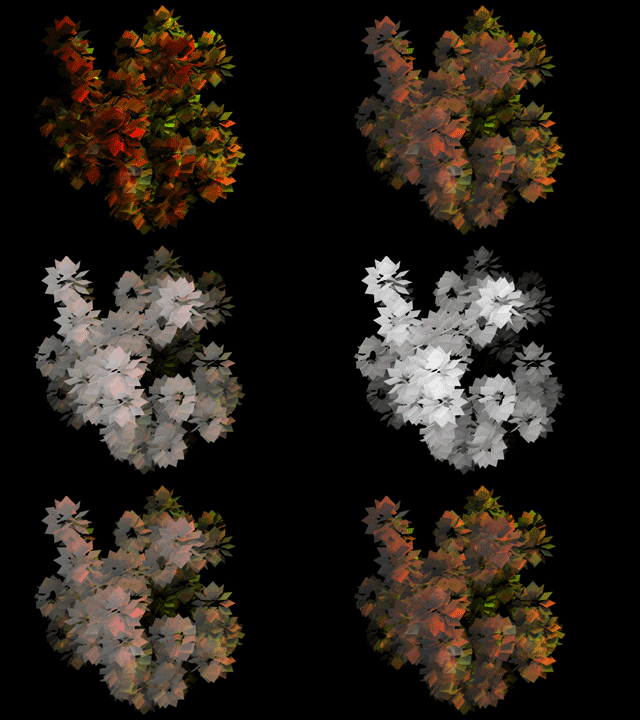
The animations below demonstrate the plate and its corresponding z-pass, used to generate a false depth of field and for selective color correction. In this case, the "correction" has been over-driven to a bright red for evident demonstration.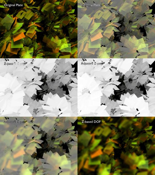
Modifying the Shader
Adding Z-depth capabilities to any shader is the simple matter of adding two lines to it's code. At right you see the beginning lines of the conditional shader to which I have added Z code. In the shader parameters a line declaring the z-info as a varying output tells the shader that this info will pass back out. Within the color calculations a second line calculates depth at any point 'P'. This value is subtracted from one to reverse the gray values so that items closest to the camera are brightest.
surface
conditionalColorDepth(float Kd = 1;
output varying float myZ = 0){
color surfcolor = 1;
normal n = normalize(N);
normal nf = faceforward(n, I);
myZ = 1-depth(P);
conditionalColorDepth(float Kd = 1;
output varying float myZ = 0){
color surfcolor = 1;
normal n = normalize(N);
normal nf = faceforward(n, I);
myZ = 1-depth(P);
Getting the Outputs from Maya
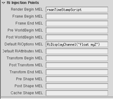
Once the shader has been modified, the Maya scene that uses it must also have certain options set so that, when it generates it's RIB at render time, the necessary options are set to recieve and understand the data. First is adding a custom output to the Default pass in the render globals. This adds the necessary Display "+untitled.myz.tiff" "tiff" "myZ" line to the RIB that opens a secondary output that will hold the z-data. Next, a particular RI Injection point (also found in the render globals) is used to add the DisplayChannel "float myZ" line to the RIB that instructs the renderer on the type of data coming out of the new output and how to handle it. Without this line, the output will fail. As seen below, adding RiDisplayChannel("float myZ") to the Default Options injection point makes it possible.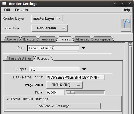
The best laid plans...
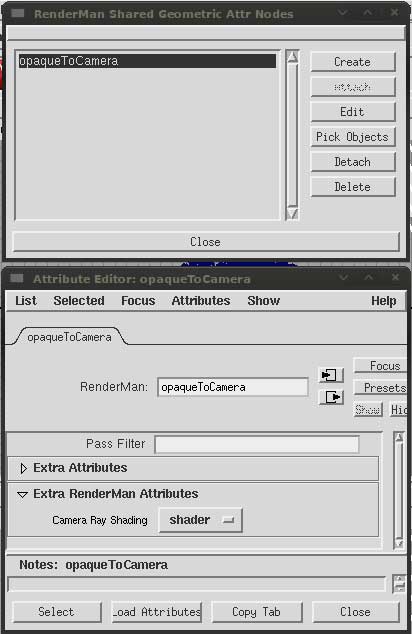
I came across a problem that was particular to the way the scene was built. Namely, the geometry was all single sided poly planes. Normally, this is no problem because Maya makes objects double-sided by defaut and Renderman would render the beauty pass correctly. However, because the z-depth is calculated within but separately from the diffuse calculations any of the backfacing polys were be ignored in the z-depth pass, leaving big holes in the channel. At first I assumed that it simply wasn't reading the double-sidedness correctly and thought to add an RiSides(2) call to the options so that everything would be forced to double-sided. Upon examining the RIB I found that the call was already present in all the shapes, passed in from Maya as it should have been. So that was clearly not going to fix the problem.After some further digging I found another option called Camera Hit Mode that determines how surfaces react to rays fired from the camera for certain calculations, in this case depth calculations. I created a Shared Geometric Attribute named opaqueToCamera to which I attached all the polys. I then added a Camera Ray Shading attribute to the SGA so that it would disseminate down to all the geometry. Setting this attribute to 'primitive' means the polys would effectively become opaque to the camera regardless of facing ratio or opacity and the depth would work properly. However, this also ignores any opacity on the surface, even those dictated by the shader itself. So I ended up rendering the scene twice. Once with camera hit set to 'shader' for a correct beauty pass (although with the incorrect z-data) and another set to 'primitive' for a correct depth pass. Normal scenes with "solid" geometry would not need to go thru this because backfacing polys would be hidden anyways and the shader with Z built in would work as planned.
